An open hardware board (KiCad) that pairs a Raspberry Pi RP2350B with a WCH CH569W. The RP2350B generates high-speed data and the CH569 streams it to a host over USB 3.0.
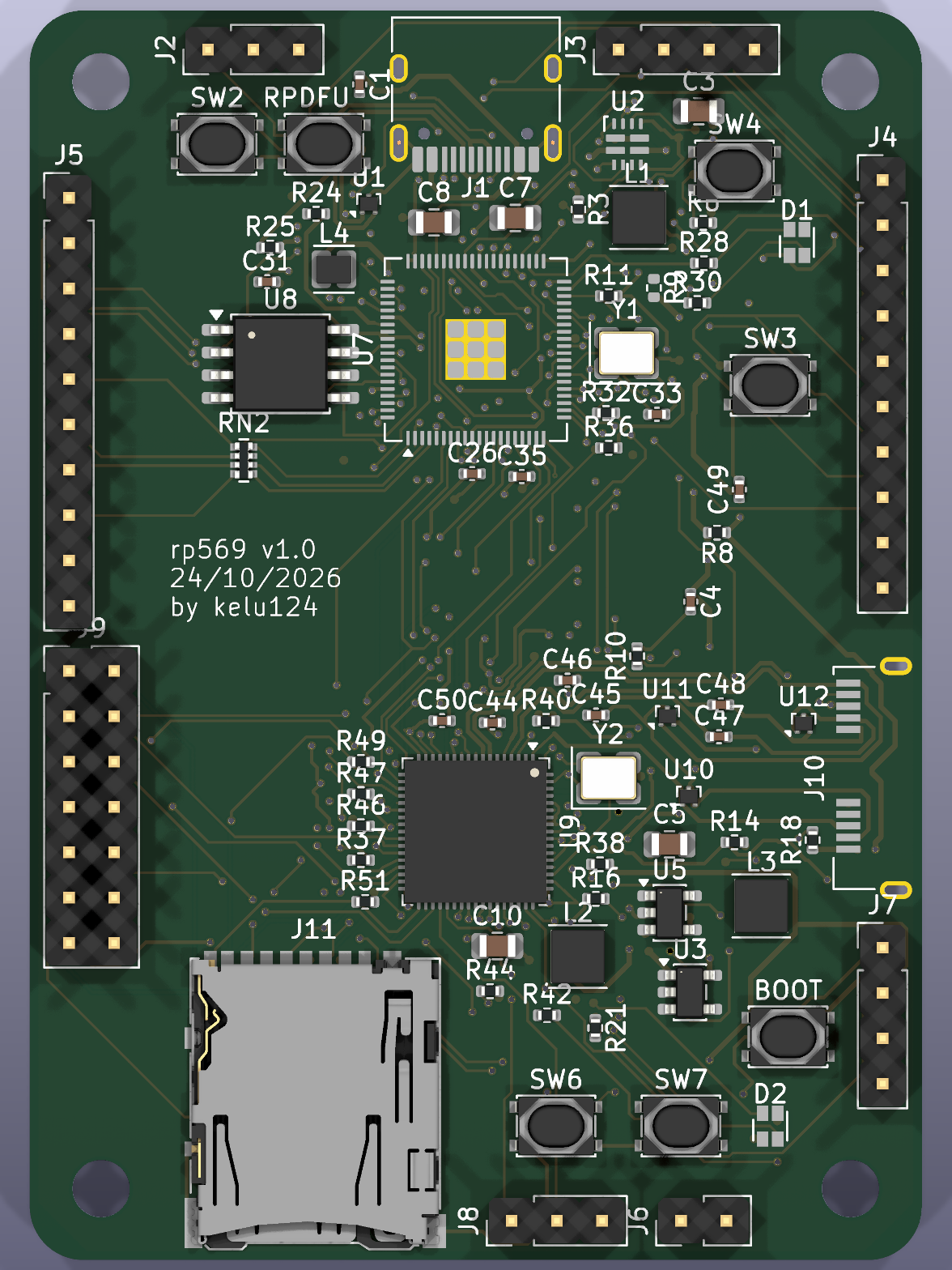
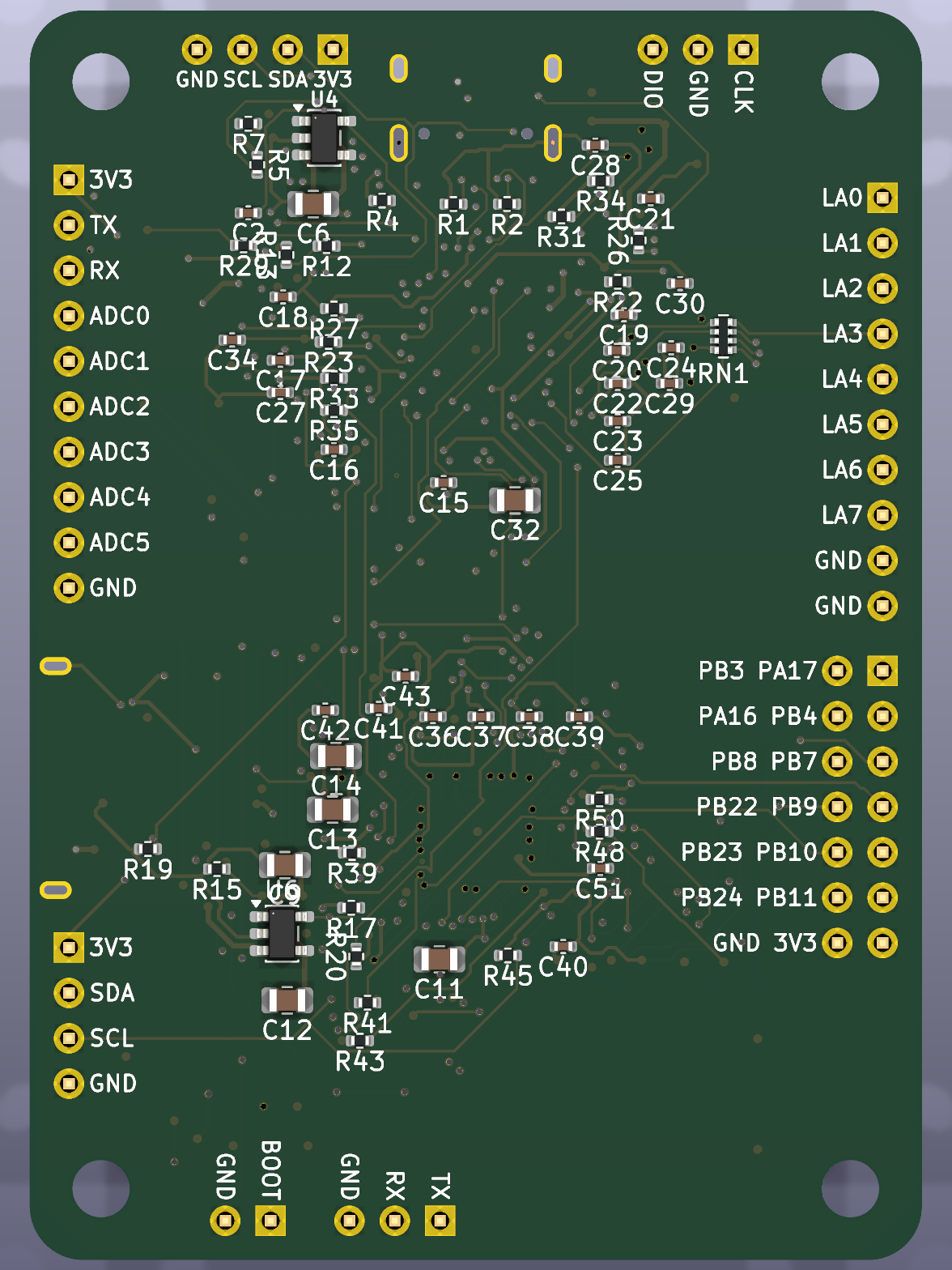
Status: v1.0 (tag v1.0). Schematic complete, PCB fully routed (4-layer, 50×70 mm, rounded corners,
parts on both sides; 0 unconnected, 0 DRC errors) and JLCPCB production files generated. Before ordering:
USB pairs as coupled pairs, silkscreen cleanup, impedance check (see docs/layout.md).
First firmware for both chips in firmware/ (builds, not run on hardware yet).
Schematic PDF. Documentation site: https://kelu124.github.io/rp569/ (GitHub Pages from docs/).
Production files (JLCPCB)
| File | Use |
|---|---|
hardware/jlcpcb/rp569-gerbers.zip |
PCB order (gerbers + drill) |
hardware/jlcpcb/rp569-bom.csv |
Assembly BOM with LCSC part numbers |
hardware/jlcpcb/rp569-cpl.csv |
Assembly placement (CPL) |
Board to fabricate: hardware/rp569-routed.kicad_pcb. Regenerate the files
with python3 hardware/gen/gen_fab.py. Two parts are not stocked by JLCPCB and must be consigned: CH569W and the
Amphenol GSB343K33HR USB3 connector (docs/bom.md).
| Top | Bottom |
|---|---|
 |
 |
Features
| Block | RP2350B | CH569W |
|---|---|---|
| USB | USB 2.0 on USB-C (firmware, debug, test control) | USB 3.0 SuperSpeed, Micro-B connector |
| Storage | QSPI flash | SD card on the eMMC/SD controller |
| User I/O | RGB LED, 2 user buttons | RGB LED, 2 user buttons |
| Boot | BOOTSEL + RUN buttons | BOOT button + jumper (force the USB bootloader on a blank chip) |
| Breakout | I2C header for extra devices | I2C header (bit-banged GPIO) |
Logic analyser: 8 input pins on the RP2350B are sampled by PIO and streamed over the parallel bus to the CH569, then to the host over USB 3.
Power: the RP2350B runs from either USB connector through a TI TPS2121 power mux, so neither back-feeds the other. The CH569 is powered from its own USB3 VBUS through a load switch that the RP2350B controls, so it can be power-cycled and forced into its bootloader during automated tests.
Links between the two chips
- 8-bit parallel bus with clock and handshake lines (8-bit because the CH569's 16-bit mode shares pins with the SD card; see
specification.mdD-003): RP2350B PIO sends, CH569 HSPI receives. - Shared I2C bus.
- UART.
- CH569 RESET# and boot-mode pins driven by the RP2350B, so the CH569 can be reflashed and power-cycled automatically during testing.
Repository layout
| Path | Content |
|---|---|
hardware/ |
KiCad project, generated from hardware/gen/board.py (run hardware/gen/build.sh); rp569-routed.kicad_pcb = routed v1.0 board |
hardware/jlcpcb/ |
JLCPCB production files: gerbers zip, BOM, CPL |
python/ |
Host library: finds the RP2350/CH569 ports by VID/PID/product/UID, one method per firmware command (python/README.md) |
firmware/ |
rp2350/ USB command line (LED, dfu, CH569 power/boot/link), ch569/ USB3 serial + SD drive with RP2350 link echo; see firmware/README.md |
datasheet/ |
Datasheets as PDF and Markdown (see datasheet/README.md) |
docs/ |
GitHub Pages site root (index.md, _config.yml): architecture.md, production.md, pinmap.md (RP2350B ↔ CH569 pin map), power.md, layout.md, bom.md (JLCPCB BOM), ch569-hardware-notes.md, hadposts/ (Hackaday log drafts) |
project/ |
Reference projects: HydraUSB3, phantomdrive (see project/README.md) |
specification.md |
Requirements (R-xx) and design decisions (D-xxx) |
CLAUDE.md, .claude/ |
Project context, todo/done logs, commit log |
References
- HydraUSB3: open-source CH569 dev kit, firmware and HSPI/USB3 drivers.
- phantomdrive: open-source CH569W encrypted USB3 drive with SD card, KiCad sources.
- RP2350 datasheet and hardware design guide.